This started when I saw an eBay listing for a Tektronix 465 for £80. The listing made it clear that there were a few issues but compared to other listings, it was pretty cheap. However, I would have to collect it from a random farm outside of Gloucester, there was no option for postage.
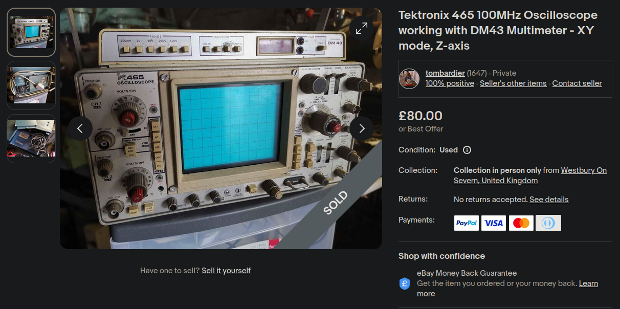
The pickup location was near a bus service, so I puchased it and went to collect it. The total cost of the oscilloscope including train/bus tickets to collect it was £105.
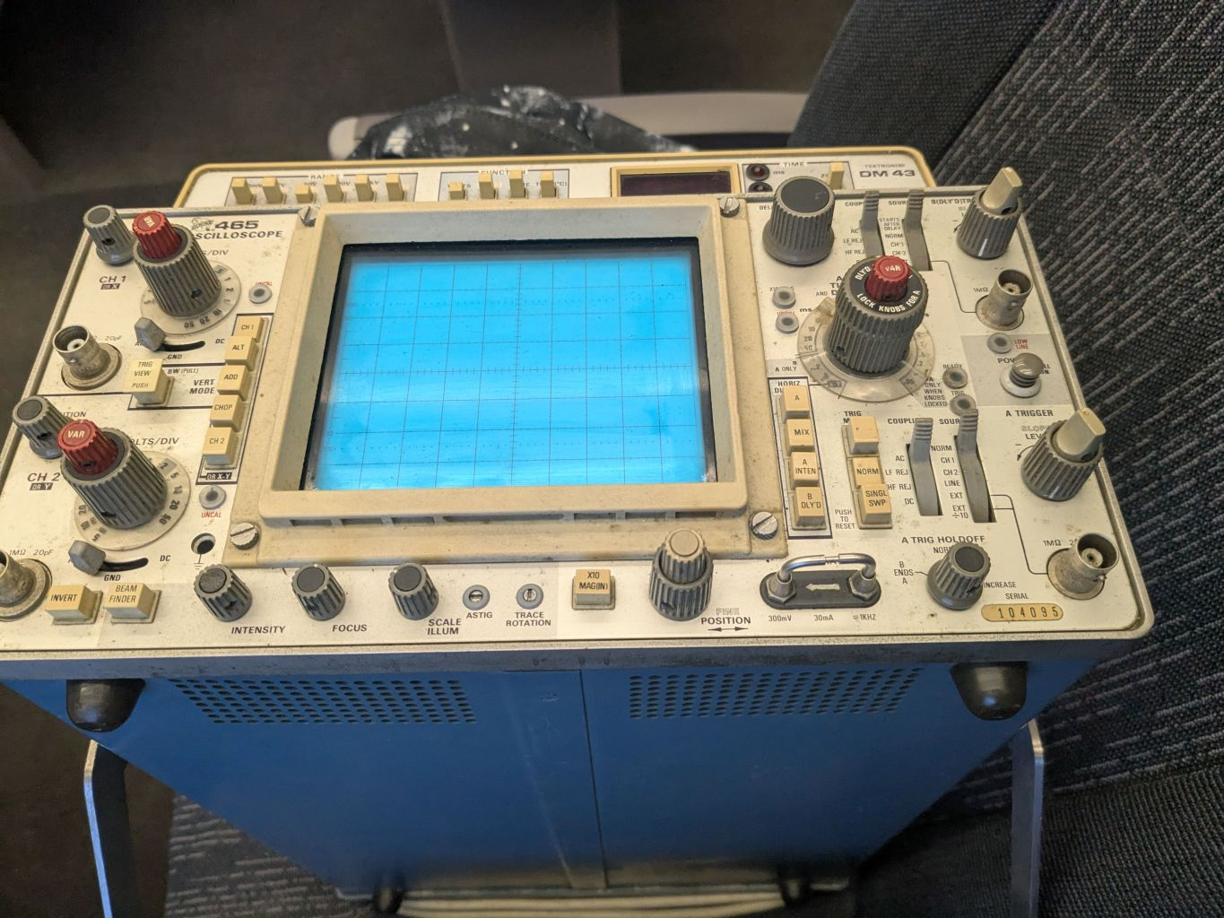
After getting it home, testing it and opening it, I discovered a few issues:
- A transistor was loose from its socket
- The channel 2 input attenuator could only switch between 3 v/div settings
- The channel 1 input coupler switch felt loose and was not switching properly
- Most of the potentiometers were scratchy
- The front panel was quite dirty
- The DM43 multimeter was not properly attached to the top.
- The blue storage pouch was not attached to the scope
The first issue was likely caused by a previous repair when reinstalling the top case. One of the capacitors on the power supply was replaced by the previous owner and that was likely the cause.
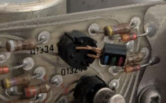
Looking at the schematic it appears to control one of the back panel outputs which was probably why the issue was not spotted by the previous owner. I bent the pins straight and reinstalled it in the socket.
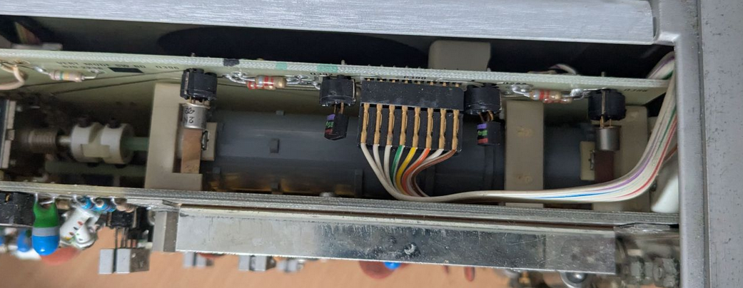
The second and third issues were a bit more complicated, as I had to remove the preamp board (the board on the left side of the scope). I was able to get the board most of the way out, although the delay line was soldered to the board and my soldering iron wasn't powerful enough to remove it.
From here I was able to access the attenuators and input couplers, they use cam switches with tiny fork shaped contacts that would connect pads on the board.
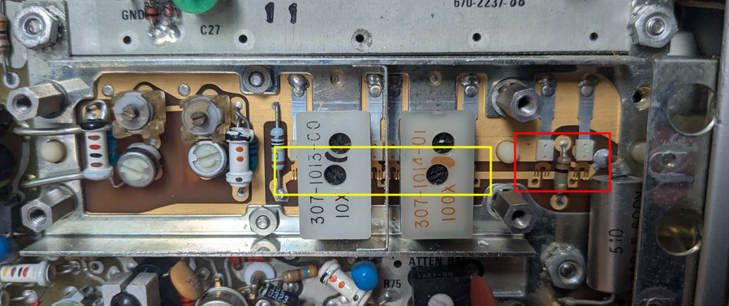
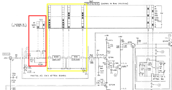
Attenuator contacts are highlighted in yellow, input coupler contacts are highlighted in red. There is a second set of contacts on the back of the board that are connected to the front ones, such that when the blue cylinder presses them, the back switches connect while the front switches disconnect. There are also 2 contacts on the right side of the schematic (left side of the photos, but on the back of the board so not visible) that act as the "fine" controls.
The "fine" contacts were working properly but the "course" contacts highlighted in yellow were not and as a result the scope would only switch between the 5mv, 10mv and 20mv settings. Cleaning these switches with isopropyl alcohol and a thin strip of paper fixed this issue.
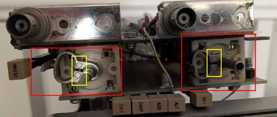
The input coupler issue was caused by the screw (highlighted in yellow) coming loose and allowing the switch (highlighted in red) to move freely on the shaft. Tightening the screw fixed this issue.
I fixed the scratchy potentiometers by loosening the screws on the back and spraying isopropyl alcohol inside them, they still aren't perfect but they are 50 years old and they work much better than they did before.
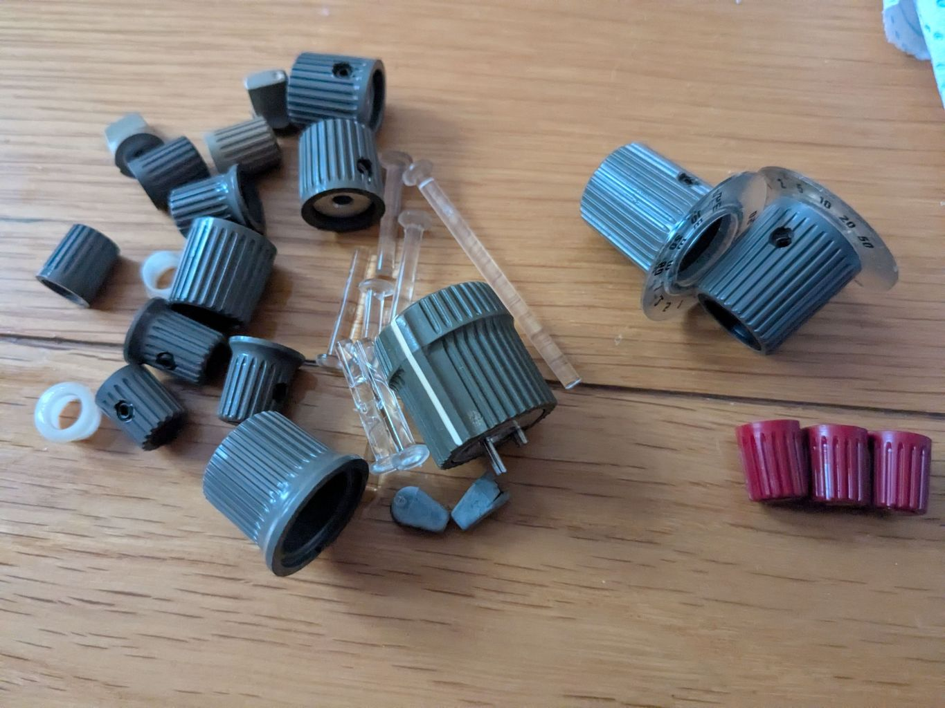
To clean the front panel I removed all the knobs and switches then soaked them in soapy water, after that I cleaned them with a brush and now they look as good as new!
The front panel itself cleaned up nicely with some isopropyl alcohol.
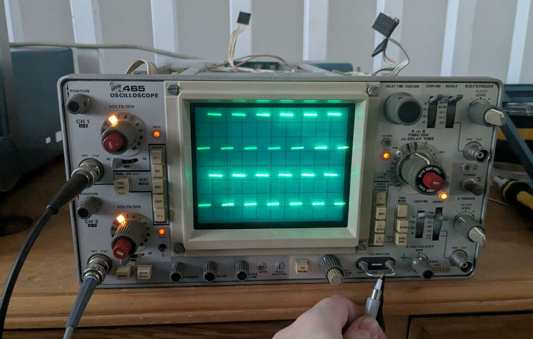
At this point I decided to test it, and it worked! The UNCAL lamps are illuminated because this thing probably hasnt been calibrated in decades, but that will be a task for another day.
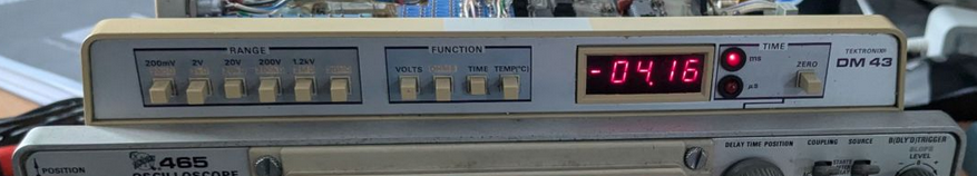
The sixth issue was simple to fix. When I got the oscilloscope the multimeter was not properly seated under the front panel surround:
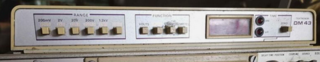
This could be resolved by reinstalling the multimeter, ensuring the plastic piece at the bottom of the multimeter was properly installed under the surround.
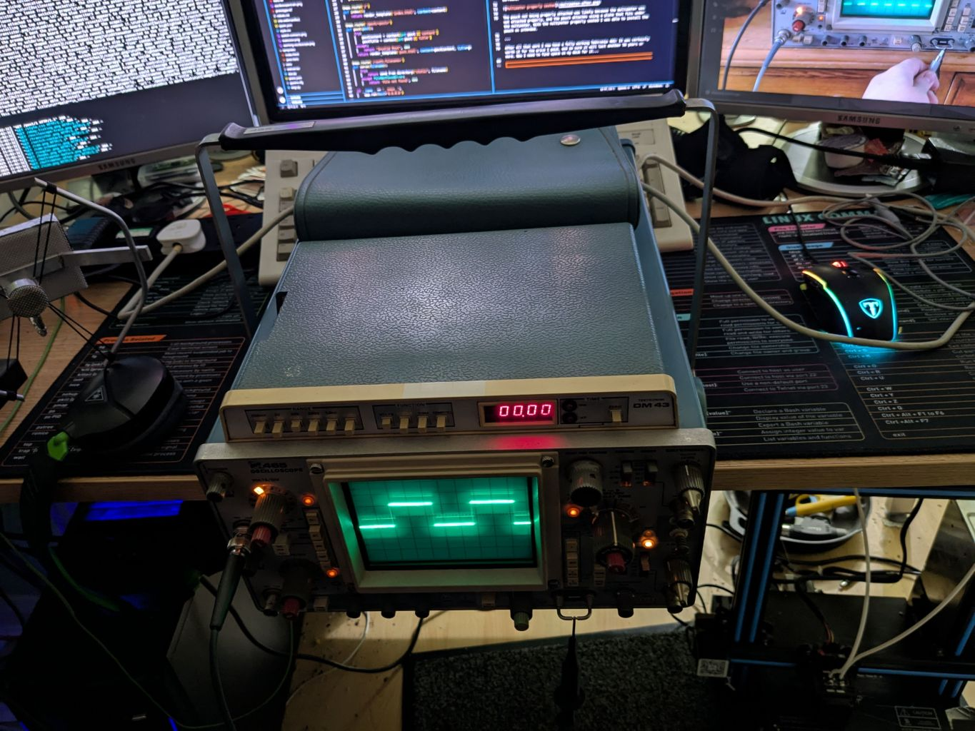
The pouch not being properly attached was likely because the multimeter was not attached properly, and the pouch attaches using a plate that fits under the multimeter. With the multimeter properly seated I was able to install the pouch as intended.
After all that work I now have a fully working Tektronix 465! It was certainly worth it for the price I paid, and I'm sure it will last another 50 years or more. Only problem now is that it's too large for my desk...
Thanks for reading!